Structure of Motores de Passo
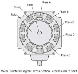
The figures below show two cross-sections of a 5-phase stepper motor. The stepper motor consists primarily of two parts: a stator e rotor. The rotor is made up of three components: rotor 1, rotor 2 e a permanent magnet. The rotor is magnetized in the axial direction so that, for example, if rotor 1 is polarized north, rotor 2 will be polarized south.
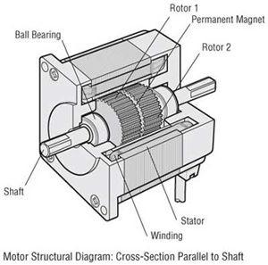
The stator has ten magnetic poles with small teeth, each pole being provided with a winding. Each winding is connected to the winding of the opposite pole so that both poles are magnetized in the same polarity when current is sent through the pair of windings. (Running a current through a given winding magnetizes the opposing pair of poles in the same polarity, i.e., north orsouth.)
The opposing pair of poles constitutes one phase. Since there are five phases, A through E, the motor is called a "5-phase stepper motor."
There are 50 small teeth on the outer perimeter of each rotor, with the small teeth of rotor 1 e rotor 2 being mechanically offset from each other by half a tooth pitch.
Excitation: To send current through a motor winding
Magnetic pole: A projected part of the stator, magnetized by excitation
Small teeth: The teeth on the rotor e stator
Principal of Operation
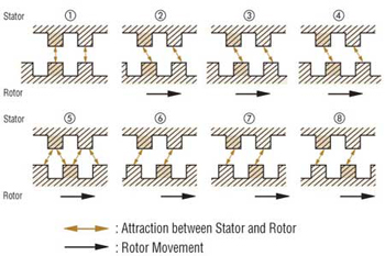
Following is an explanation of the relationship between the magnetized stator small teeth e rotor small teeth.
When Phase "A" is Excited
When phase A is excited, its poles are polarized south. This attracts the teeth of rotor 1, which are polarized north, while repelling the teeth of rotor 2, which are polarized south. Therefore, the forces on the entire unit in equilibrium hold the rotor stationary. At this time, the teeth of the phase B poles, which are not excited, are misaligned with the south-polarized teeth of rotor 2 so that they are offset 0.72˚. This summarizes the relationship between the stator teeth e rotor teeth with phase A excited.
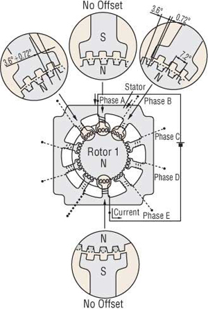
When Phase "B" is Excited
When excitation switches from phase A to B, the phase B poles are polarized north, attracting the south polarity of rotor 2 e repelling the north polarity of rotor 1.
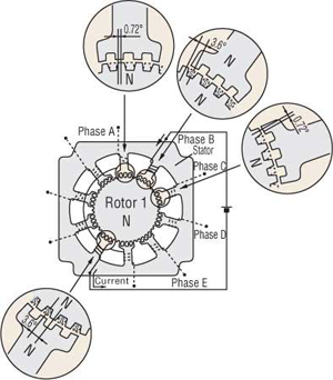
In other words, when excitation switches from phase A to B, the rotor rotates by 0.72˚. As excitation shifts from phase A, to phases B, C, D e E, then back around to phase A, the stepping motor rotates precisely in 0.72˚ steps. To rotate in reverse, reverse the excitation sequence to phase A, E, D, C, B, then back around to phase A.
High resolution of 0.72˚ is inherent in the mechanical offset between the stator e rotor, accounting for the achievement of precise positioning without the use of an encoder orother sensors. High stopping accuracy of }3 arc minutes (with no load) is obtained, since the only factors affecting stopping accuracy are variations in the machining precision of the stator e rotor, assembly precision e DC resistance of windings.
The driver performs the role of phase switching, e its timing is controlled by a pulse-signal input to the driver. The example above shows the excitation advancing one phase at a time, but in an actual stepper motor an effective use of the windings is made by exciting four orfive phases simultaneously.
Basic Characteristics of Motores de Passo
An important point to consider in the application of stepper motors is whether the motor characteristics are suitable to the operating conditions.
The following sections describe the characteristics to be considered in the application of stepper motors.
The two main characteristics of stepper motor performance are:
- Dynamic Characteristics: These are the starting e rotational characteristics of a stepper motor, mainly affecting the machinery’s movement e cycling time.
- Static Characteristics: These are the characteristics relating to the changes in angle that take place when the stepper motor is in standstill mode, affecting the machinery’s level of precision.
Dynamic Characteristics
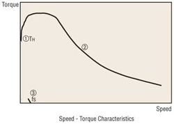
Speed – Torque Characteristics The figure above is a characteristics graph showing the relationship between the speed e torque of a driven stepper motor. These characteristics are always referred to in the selection of a stepper motor. The horizontal axis represents the speed at the motor output shaft, e the vertical axis represents the torque. The speed – torque characteristics are determined by the motor e driver, e are greatly affected by the type of driver being used.
- Maximum holding torque (TH) The maximum holding torque is the stepper motor’s maximum holding power (torque) when power is supplied (at rated current) when the motor is not rotating.
- Pullout torque The pullout torque is the maximum torque that can be output at a given speed. When selecting a motor, be sure the required torque falls within this curve.
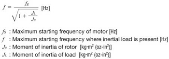
- Maximum starting frequency (fS) This is the maximum pulse speed at which the motor can start orstop instantly (without an acceleration/deceleration time) when the stepper motor’s friction load e inertial load are 0. Driving the motor at a pulse speed in excess of this rate will require a gradual acceleration ordeceleration. This frequency will decrease when an inertial load is added to the motor. Refer to the inertial load – starting frequency characteristics below.
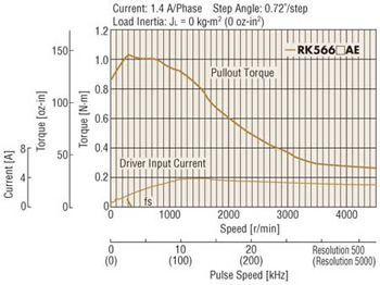
Maximum response frequency (fr) This is the maximum pulse speed at which the motor can be operated through gradual acceleration ordeceleration when the stepper motor’s friction load e inertial load are 0. The figure below shows the speed – torque characteristics of a 5-phase stepper motor e driver package.
Inércial Load – Starting Frequency Characteristics These characteristics show the changes in the starting frequency caused by the load inertia. Since the stepper motor’s rotor e load have their own moment of inertia, lags e advances occur on the motor axis during instantaneous starting e stopping. These values change with the pulse speed, but the motor cannot follow the pulse speed beyond a certain point, so that missteps result. The pulse speed immediately before the occurrence of a misstep is called the starting frequency.
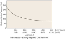
Changes in maximum starting frequency with the inertial load may be approximated via the following formula:
Vibration Characteristics
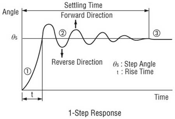
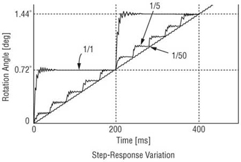
The stepper motor rotates through a series of stepping movements. A stepping movement may be described as a 1-step response, as shown below:
1. A single pulse input to a stepper motor at a standstill accelerates the motor toward the next stop position.
2. The accelerated motor rotates through the stop position, overshoots a certain angle, e is pulled back in reverse.
3. The motor settles to a stop at the set stop position following a damping oscillation.
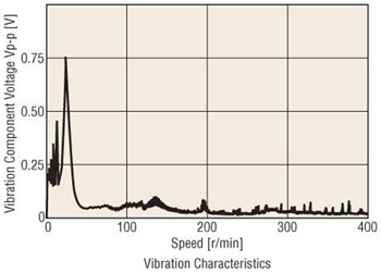
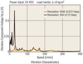
Vibration at low speeds is caused by a step-like movement that produces this type of damping oscillation. The vibration characteristics graph below represents the magnitude of vibration of a motor in rotation. The lower the vibration level, the smoother the motor rotation will be.
Static Characteristics
Angle – Torque Characteristics: The angle – torque characteristics show the relationship between the angular displacement of the rotor e the torque externally applied to the motor shaft while the motor is excited at the rated current. The curve for these characteristics is shown below:
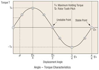
The following illustrations show the positional relationship between the rotor teeth e stator teeth at the numbered points in the diagram above. When held stable at point (1) the external application of a force to the motor shaft will produce torque T (+) in the left direction, trying to return the shaft to stable point (1). The shaft will stop when the external force equals this torque at point (2).
If additional external force is applied, there is an angle at which the torque produced will reach its maximum at point (3). This torque is called the maximum holding torque TH.
Application of external force in excess of this value will drive the rotor to an unstable point (5) e beyond, producing torque T (−) in the same direction as the external force, so that it moves to the next stable point (1) e stops.
Stable Points: Points where the rotor stops, with the stator teeth e rotor teeth are exactly aligned. These points are extremely stable, e the rotor will always stop there if no external force is applied.
Unstable Points: Points where the stator teeth e rotor teeth are half a pitch out of alignment. A rotor at these points will move to the next stable point to the left orright, even under the slightest external force.
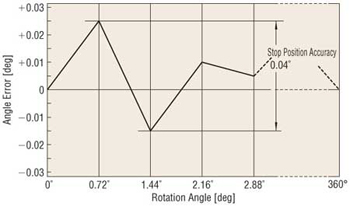
Angle Accuracy
Under no load conditions, a stepper motor has an angle accuracy within ±3 arc minutes (±0.05˚). The small error arises from the difference in mechanical precision of the stator e rotor e a small variance in the DC resistance of the stator winding. Generally, the angle accuracy of the stepper motor is expressed in terms of the stop position accuracy.
Stop Position Accuracy: The stop position accuracy is the difference between the rotor’s theoretical stopping position e its actual stopping position. A given rotor stopping point is taken as the starting point, then the stop position accuracy is the difference between the maximum (+) value e maximum (−) value in the set of measurements taken for each step of a full rotation.
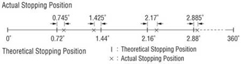
The stop position accuracy is within ±3 arc minutes (±0.05˚), but only under no load conditions. In actual applications there is always the same amount of friction load. The angle accuracy in such cases is produced by the angular displacement caused by the angle – torque characteristics based upon the friction load. If the friction load is constant, the displacement angle will be constant for uni-directional operation.
However, in bi-directional operation, double the displacement angle is produced over a round trip. When high stopping accuracy is required, always position in the same direction.
Excitation Sequence of Motor de Passo e Driver Packages
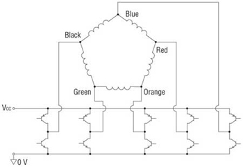
Every 5-phase motor e driver package listed in our catalog consists of a New Pentagon, five-lead wire motor e a driver incorporating a special excitation sequence. This combination, which is proprietary to Oriental Motor, offers the following benefits:
- Simple connections for five leads
- Low vibration
The following sections describe the wiring e excitation sequence.
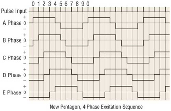
New Pentagon, 4-Phase Excitation: Full Step Sistema (0.72˚/step)
This is a system unique to the 5-phase motor, in which four phases are excited. The step angle is 0.72˚ (0.36˚). It offers a great damping effect, e therefore stable operation.
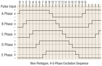
New Pentagon, 4-5 Fases Excitation: Half-Step Sistema (0.36˚/step)
A step sequence of alternating the 4-phase e 5-phase excitation produces rotation at 0.36˚ per step. One rotation may be divided into 1000 steps.
Drivers de Motor de Passo
There are two common systems of driving a stepper motor: constant current drive e constant voltage drive. The circuitry for the constant voltage drive is simpler, but it’s relatively more difficult to achieve torque performance at high speeds.
The constant current drive, on the other hand, is now the most commonly used drive method, since it offers excellent torque performance at high speeds. All Oriental Motor’s drivers use the constant current drive system.
Overview of the Constant Corrente Drive Sistema
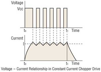
The stepper motor rotates through the sequential switching of current flowing through the windings. When the speed increases, the switching rate also becomes faster e the current rise falls behind, resulting in lost torque. The chopping of a DC voltage that is far higher than the motor’s rated voltage will ensure the rated current reaches the motor, even at higher speeds.
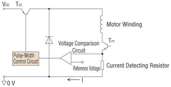
The current flowing to the motor windings, detected as a voltage through a current detecting resistor, is compared to the reference voltage. Corrente control is accomplished by holding the switching transistor Tr2 ON when the voltage across the detecting resistor is lower than the reference voltage (when it hasn’t reached the rated current), orturning Tr2 OFF when the value is higher than the reference voltage (when it exceeds the rated current), thereby providing a constant flow of rated current.
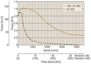
Differences between Entrada CA e Entrada CC Characteristics
A stepper motor is driven by a DC voltage applied through a driver. In Oriental Motor’s 24 VCC input motor e driver packages, 24 VCC is applied to the motor. In the 100-115 VCA motor e driver packages the input is rectified to DC e then approximately 140 VCC is applied to the motor. (Certain products are exceptions to this.)
This difference in voltages applied to the motors appears as a difference in torque characteristics at high speeds. This is due to the fact that the higher the applied voltage is, the faster the current rise through the motor windings will be, facilitating the application of rated current at higher speeds.
Thus, the AC input motor e driver package has superior torque characteristics over a wide speed range, from low to high speeds, offering a large speed ratio. It is recommended that AC input motor e driver packages, which are compatible with a wider range of operating conditions, be considered for your applications.
Microstep Drive Technology
Microstep drive technology is used to divide the basic step angle (0.72˚) of the 5-phase stepping motor into smaller steps (até a maximum of 250 divisions) without the use of a speed reduction mechanism.
◇ Microstep Drive Technology
The stepper motor moves e stops in increments of the step angle determined by the rotor e stator’s salient pole structure, easily
achieving a high degree of precision in positioning. The stepper motor, on the other hand, causes the rotor speed to vary because
the motor rotates in step angle increments, resulting in resonance orgreater vibration at a given speed.
Microstepping is a technology that achieves low resonance, low noise operation at extremely low speeds by controlling the flow of
electric current fed to the motor coil e thereby dividing the motor’s basic step angle into smaller steps.
- The motor’s basic step angle (0.72˚/full step) can be divided into smaller steps ranging from 1/1 to 1/250. Microstepping thus ensures smooth operation.
- With the technology for smoothly varying the motor drive current, motor vibration can be minimized for low noise operation.
◇ Up to 250 Microsteps
Thanks to the microstep driver, different step angles (16 steps até 250 divisions) can be set to two step angle setting switches. By controlling the input signal for step angle switching via an external source, it is possible to switch the step angle between the levels set for the respective switches.
Características of Microstep Drive
● Baixa vibração
Microstep drive technology electronically divides the step angle into smaller steps, ensuring smooth incremental motion at low speeds e significantly reducing vibration. While a damper orsimilar device is generally used to reduce vibration, the low vibration design employed for the motor itself — along with the microstep drive technology — minimizes vibration more effectively. Anti-vibration measures can be dramatically simplified, so it’s ideal for most vibration sensitive applications e equipment.
● Baixo Nivel de Ruído
Microstep drive technology effectively reduces the vibration related noise level at low speeds, achieving low noise performance. The motor demonstrates outstanding performance in even the most noise sensitive environment.
● Improved Controllability
The New Pentagon microstep driver, with its superior damping performance, minimizes overshoot e undershoot in response to step changes, accurately following the pulse pattern e ensuring improved linearity. In addition, shock normally resulting from the motions of starting e stopping can be lessened.
Motor de Passo e Driver Package
Overview of the Control Sistema
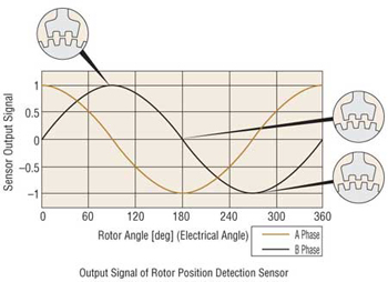
◇ The Sensor to Detect Rotor’s Position
A rotor position detection sensor is built into the counter end of the motor output shaft:
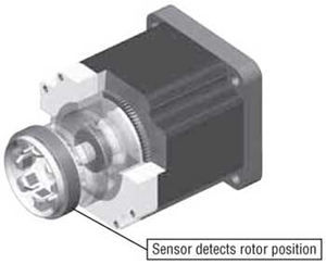
The sensor winding detects changes in magnetic reluctance due to the angular position of the rotor.
Featuring Innovative Circuito Fechado Control
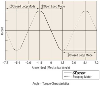
The deviation counter calculates the deviation (lag/advance) of the rotor’s actual angular position with regard to the position command by the pulse signal. The calculation result is used to detect a “misstep region” e operate the motor by switching between open loop e closed loop modes.
- If the positioning deviation is less than }1.8˚, the motor runs in the open loop mode.
- If the positioning deviation is }1.8˚ ormore, the motor runs in closed loop mode.

In the closed loop mode, motor-winding excitation is controlled so that maximum torque is developed for the given angular position of the rotor. This control method eliminates unstable points (misstep region) in the angle – torque characteristics.
Características of AlphaStep
◇ Improved Motor de Passo Performance
- At high speeds will not “misstep.” Therefore, unlike conventional stepper motors, the operation will be free of the following restrictions:
- Restrictions on acceleration/deceleration rates e inertia ratio stemming from the pulse profile of the controller.
- Restrictions on starting pulse speed caused by “misstep.”
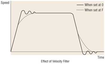
- Use the velocity filter to adjust responsiveness while starting/ stopping. The responsiveness of starting/stopping can be adjusted with 16 configurações without changing the controller data (starting pulse, acceleration/deceleration rates). This feature is intended to reduce shock to the work e vibration during low speed operation.
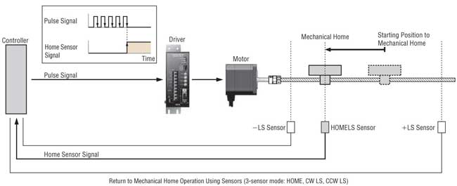
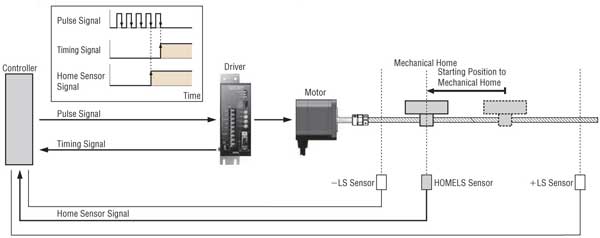
Return to Mechanical Home Operation Using Excitation Timing Signal
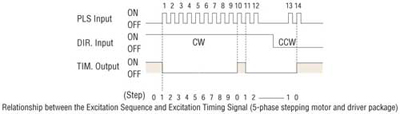
● Excitation Timing Signal
The excitation timing (TIM.) signal is output when the driver is initially exciting the stepper motor (step "0"). Oriental Motor's 5-phase stepper motor e driver packages perform initial excitation when the power is turned on, e advance the excitation
sequence each time a pulse signal is input, completing one cycle when the motor shaft rotates 7.2˚.
Use these timing signals when it is necessary to perform highly reproducible return to mechanical home operation. The following sections describe stepper motor return to mechanical home operation e the use of timing signals.
● Return to Mechanical Home Operation for Motores de Passo
When turning on the power to start automated equipment orrestarting the equipment after a power failure, it is necessary to return stepper motors to their standard position. This operation is called the "return to mechanical home operation."
The return to mechanical home operation for stepper motors uses home sensors to detect the mechanical component used for the positioning operation. When the detected signals are confirmed, the controller stops the pulse signal, e the stepper motor is stopped. The accuracy of the home position in such a return to mechanical home operation depends on the detection performance of the home sensors. As the detection performance of the home sensors varies according to factors such as the ambient temperature e approach speed of the mechanism detection area, it's necessary to reduce these factors for applications that require a highly reproducible mechanical home position detecting.
● Improved Reproducibility Using Excitation Timing Signal
A method of ensuring that the mechanical home position does not vary due to variations in the detection performance of the home sensors, is to stop the pulse signal by logically multiplying with the timing signal. As the timing signal is output at initial excitation, if the pulse signal is stopped when the timing signal is output, the mechanical home position will always be determined at initial excitation.
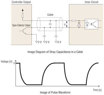
Relationship between Cabo Comprimento e Transmission Frequency
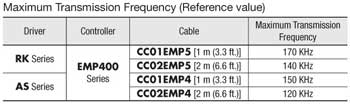
As the pulse line cable becomes longer, the maximum transmission frequency decreases. Specifically, the resistive component e stray capacitance of the cable cause the formation of a CR circuit, thereby delaying the pulse rise e fall times. Stray capacitance in a cable occurs between electrical wires e ground planes. However, it is difficult to provide distinct numerical data, because conditions vary according to the cable type, layout, routing e other factors.
The transmission frequency when operated in combination with our products (actual-measurement reference values) are shown below:
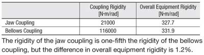
Effect of Acoplamentos Rigidity on Equipment
The specifications that indicate coupling performance include permissible load, permissible speed, torsional spring constant, backlash (play) in the coupling, e permissible misalignment. In practice, when selecting couplings for equipment that requires high positioning performance orlow vibration, the primary selection criteria would be "rigid, with no backlash." However, in some cases coupling rigidity has only a slight effect on the equipment's overall rigidity.
This section provides an example by comparing the overall rigidity of equipment consisting of a ball screw drive in two applications where a jaw coupling such as an MCS e a bellows coupling offering higher rigidity are used. (Data is taken from KTR's technical document, for which reason the coupling dimensions differ from the products offered by Oriental Motor.)
Overview of Test Equipment
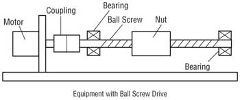
Specifications of Parts
Torsional spring constant of jaw coupling
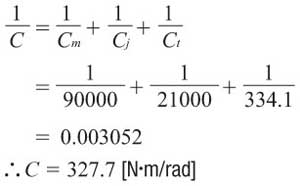
Cj = 21000 [N・m/rad]
Torsional spring constant of bellows coupling
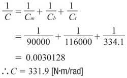
Cb = 116000 [N・m/rad]
Servo motor rigidity
Cm = 90000 [N・m/rad]
Ball screw lead
h = 10 [mm]
Ball screw root circle diameter
d = 28.5 [mm]
Ball screw length
L = 800 [mm]
Bearing rigidity in axial direction
Rbrg = 750 [N/μm]
Rigidity in axial direction of ball screw nut
Rn = 1060 [N/μm]
Modulus of elasticity of ball screw
Rf = 165000 [N/mm2]
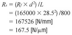
1. Obtain the torsional rigidity of the ball screw, bearing e nut. The rigidity in the axial direction of the ball screw Rs is calculated as follows:
Therefore, the total rigidity in the axial direction of the ball screw, bearing e nut Rt is calculated as follows:
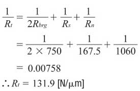
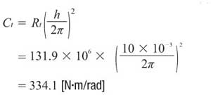
This rigidity in the axial direction is applied as torsional rigidity Ct.
2. Obtain the overall equipment rigidity C when a jaw coupling is used.
3. Obtain the overall equipment rigidity C when a bellows coupling is used.
4. Calculation Results