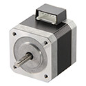

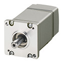


Motor de Passo Redutor
Role of the Gearhead
The role of a gearhead is closely related to motor development. Originally, when the AC motor was a simple rotating device, the gearhead was mainly used to change the motor speed e as a torque amplifier. With the introduction of motors incorporating speed control functions, the primary role of the gearhead was to amplify torque.
But with the wide acceptance of stepping motors to meet the requirements for control of speed e position, gearheads found new purposes, including the amplification of torque, improvement in permissible inertia e reduction of motor vibration. Furthermore, the accurate positioning capability of motors has created a demand for high-precision, backlash-free gearheads, unlike the conventional gearheads for AC motors.
Oriental Motor, keeping up with these trends, has been developing specific gearheads having optimal characteristics needed to preserve the characteristics of the motor with which it is used. Redutor for AC motors are designed with emphasis on high permissible torque, long life, low noise e a wide range of gear ratios to use continuously for power source.
By contrast, gearheads for stepping motors are designed for high accuracy positioning, where a high accuracy, high permissible torque e high speed operation are important. The following sections describe these gearheads in detail.
Motor de Passo Gears
Since stepper motors e other control motors are designed to allow accurate positioning, the gearheads used for these motors must provide the same level of accuracy. Accordingly, Oriental Motor has developed a mechanism to minimize backlash in gears used with stepper motors in order to ensure low backlash properties.
Generally speaking, a stepper motor features greater output torque than an AC motor of the same frame size. Therefore, the stepper motor is designed to accommodate high torque e high speed so as not to diminish the motor's characteristics.
The basic principles e structures of typical control motor gears are explained below.
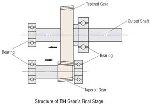
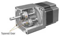
TH (Taper Hobbed) Gears
◇ Principle e Structure
Tapered gears are used for the final stage of the spur gear's speed reduction mechanism e the meshing gear. The tapered gear is produced through a continuous profile shifting toward the shaft. The tapered gears are adjusted in the direction of the arrows, as shown
in the figure below, to reduce backlash.
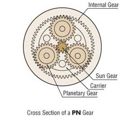
Planetary (PN) Gears
◇ Principle e Structure
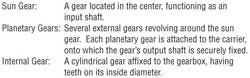
The planetary gear mechanism is comprised mainly of a sun gear, planetary gears e an internal tooth gear. The sun gear is installed on the central axis (in a single stage type, this is the motor shaft) surrounded by planetary gears enclosed in an internal tooth gear centered on the central axis. The revolution of planetary gears is translated into rotation of the output shaft via carriers.
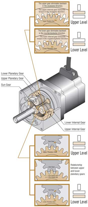
The PN gear employs the planetary gear speed-reduction mechanism. The PN gear achieves the specified backlash of three arc minutes through the improved accuracy of its components e the backlash-elimination mechanism. That mechanism is comprised of two sets of internal e planetary gears on the upper e lower levels with the internal gear teeth twisted in the circumferential direction. The upper internal gears e planetary gears reduce clockwise backlash; the lower internal gears e planetary gears reduce counterclockwise backlash.
◇ High Permissible Torque
Nos mecanismos convencionais de redução da velocidade do engrenagem, as engrenagens engrenam uma a uma, de modo que a quantidade de torque é limitada pela força de cada engrenagem individual. Por outro lado, no mecanismo de redução da velocidade da engrenagem planetária, pode ser transmitida uma maior quantidade de torque, já que o torque é distribuído através da dispersão através de várias engrenagens planetárias.
The torque applied to each gear in the planetary gear speed reduction mechanism is obtained through the following formula:
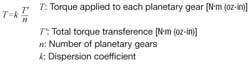
The dispersion coefficient indicates how evenly the torque is dispersed among the individual planetary gears. The smaller the coefficient, the more evenly the torque is dispersed e the greater the amount of torque that can be transferred. To evenly distribute the transferred torque, each component must be accurately positioned.
◇ Gear Characteristics
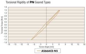
Torsional Rigidity
When a load is applied to the PN gear's output shaft, displacement (torsion) occurs by the spring characteristics of gear. The graph below shows data for torsion angles measured by gradually increasing e decreasing the load on the output shaft in the forward e backward directions. Since the PN gear's backlash is maintained at orbelow three arc minutes, the torsional torque will not result in an abrupt increase in torsion angle.
Harmonic Gears
◇ Principle e Structure
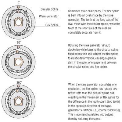
The harmonic gear offers unparalleled precision in positioning e features a simple structure utilizing the metal's elastodynamics property. It is comprised of three basic components: a wave generator, flex spline e circular spline.
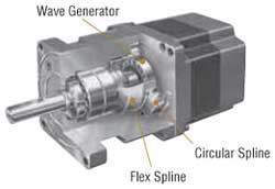
● Wave Generator
The wave generator is an oval-shaped component with a thin ball bearing placed around the outer circumference of the oval cam. The bearing's inner ring is attached to the oval cam, while the outer ring is subjected to elastic deformation via the balls. The wave generator is mounted onto the motor shaft.
● Flex Spline
The flex spline is a thin, cup-shaped component made of elastic metal, with teeth formed along the outer circumference of the cup's opening. The gear's output shaft is attached to the bottom of the flex spline.
● Circular Spline
The circular spline is a rigid internal gear with teeth formed along its inner circumference. These teeth are the same size as those of the flex spline, but the circular spline has two more teeth than the flex spline. The circular spline is attached to the gearbox along its outer circumference.
◇ Precision
Unlike conventional spur gears, the harmonic gear is capable of averaging the effects of tooth pitch errors e accumulated pitch errors to the rotational accuracy, thus achieving highly accurate, non-backlash performance. However, the gear's own torsion may become the cause of a problem when performing ultra-high accuracy positioning of two arc minutes orless. When using a harmonic gear for ultra-high accuracy positioning, remember the following three points.
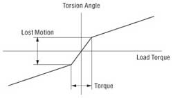
● Lost Motion
Lost motion is the total value of the displacement produced when about 5% of permissible torque is applied to the gear's output shaft. Since harmonic gears have no backlash, the measure indicating the gear's accuracy is represented as lost motion.
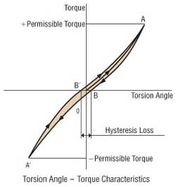
● Hysteresis Loss
When torsion torque is gradually applied to the gear output shaft until it reaches the permissible torque in the clockwise orcounterclockwise direction, the torsion angle will become smaller as the torque is reduced. However, the torsion angle never reaches 0, even when fully returned to its initial level. This is referred to as "hysteresis loss," as shown by B-B' in the figure. Harmonic gears are designed to have a hysteresis loss of less than two minutes. When positioning in the clockwise orcounterclockwise direction, this hysteresis loss occurs even with a friction coefficient of 0. When positioning to two minutes orless, positioning must be done in a single direction.
● Torque – Torsion Characteristics
Displacement (torsion) is produced by the gear's spring constant when a load is applied to the output shaft of the harmonic gear. The amount of this displacement, which is caused when the gear is driven under a friction load, is the same as the value when the motor shaft is held fixed e torsion torque is applied to the gear's output shaft.
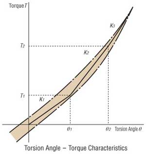
The amount of displacement (torsion angle) can be estimated through use of a formula, as shown below. The harmonic gear's torsion angle – torque characteristics curve is not linear, e the characteristics can be expressed in one of the following three formulas depending on the load torque:
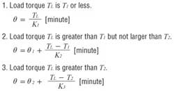
Torsion angles obtained by these formulas are for individual harmonic gears.
Advantages of Geared Motores de Passo
Geared stepper motors are designed mainly for speed reduction, higher torque e high resolution as well as the following purposes:
- Downsizing (smaller frame size e lower mass)
- High rigidity (making the motor less prone to the effects of fluctuation in friction load)
- Shorter positioning time e improved safety margin for inertial loads
- Low vibration
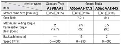
To further explain these four purposes using examples, comparisons will be made below between a standard type motor e a geared motor, both of which have similar output torque e permissible torque. If no problem exists in terms of speed, the standard type motor may be replaced by the geared motor.
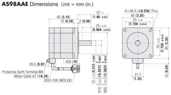
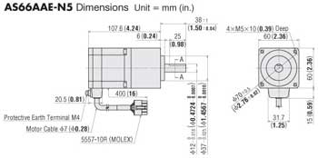
- Downsizing (smaller frame size e lower mass) A standard type motor may be switched to a smaller geared motor as long as both motors operate at equivalent torque. For example, a standard type motor with a frame size of □85 mm (□3.35 in.) can be replaced by the geared motor with a frame size of □60 mm (□2.36 in.), thereby reducing the mass from 1.8 kg (4.0 lb.) to 1.5 kg (3.3 lb.) (comparison between AS98AAE e AS66AAE-N5).
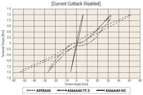
● High Rigidity (making the motor less prone to the effects of fluctuation in friction load)
With the motor's power on, the output shaft is subjected to torsion applied externally to measure the amount of displacement (torsion angle) for comparison of rigidity. At a given torque, the smaller displacement (torsion angle) means higher rigidity. For example, the AS66AAE-T7.2 geared motor receives backlash effects at a light load of 0.1 N・m torsional torque, but becomes less prone to twisting than the AS98AAE as the torsion increases. The AS66AAE-N5 motor receives little in the way of backlash effects at a light load, e maintains high rigidity throughout the entire torque range.
Comparison of Torsional Rigidity between Padrão Motor e Redutor Motor
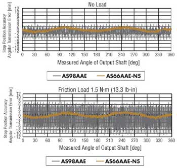
Positioning accuracy against the fluctuating friction load is an important determinant of motor rigidity. Positioning accuracy can be measured by the stop position accuracy (angular transmission error for the geared motor). The stop position accuracy (angular transmission error) refers to the difference between the theoretical rotation angle (this is the rotation angle calculated from the number of input pulses) e the actual output shaft's rotation angle. The error closer to 0 represents higher rigidity.
The standard type AS98AAE motor e AS66AAE-N5 geared motor are compared by measuring the stop position accuracy (angular transmission error) under no load e a friction load, at 0.36˚ intervals for a rotation. The results of comparison show that standard type motor's stop position accuracy significantly increases when the load is applied while the geared motor's angular transmission error barely changes, even when the load is applied. In other words, the geared motor is more resistant to fluctuations in friction load, thus achieving more stable positioning. This feature applies to any type of geared motor. Therefore, geared motors are more effective for positioning operation for vertical drive e other applications in which friction load fluctuates due to the varying quantity e weight of the load.
Comparison of Stop Position Accuracy (Angular transmission error) between AS98AAE e AS66AAE-N5:
● Shorter Positioning Time e Improved Safety Margin for Inércial Loads
To drive a large inertial load within a short period of time, the use of a geared motor will achieve a shorter positioning time than a standard type motor.
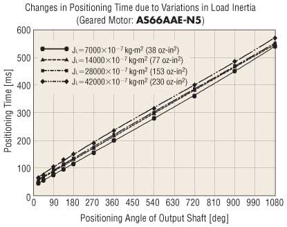
Assume that the standard type AS98AAE motor is connected to inertial loads that are 5 e 30 times the rotor inertia, e that each of these inertial loads is connected to the geared type AS66AAE-N5 motor. The shortest positioning time for each rotation angle is measured as shown in the graphs below.
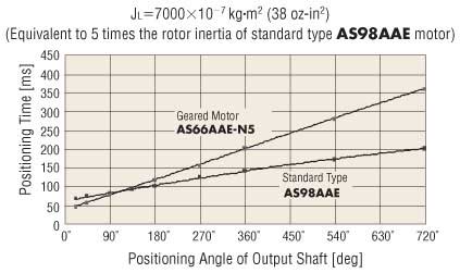
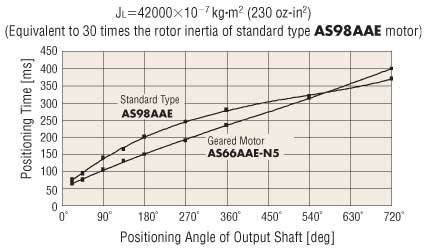
The geared motor is more effective in reducing the positioning time for a smaller positioning angle e a larger inertial load. The geared motor tends to achieve shorter positioning time in a wider range of positioning angles with a larger inertial load.
The geared motor reduces positioning time for the following reasons:
- Inércial load to the motor shaft can be reduced through the use of gears, thereby ensuring quick acceleration e deceleration starting.
![]()
Another advantage of the geared motor is its ability to maintain a consistent positioning time regardless of changes in inertial load. The graphs below show changes in the shortest positioning time of the standard type motor e geared motor when each motor is subjected to variations in inertial load.
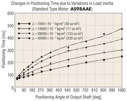
While the shortest positioning time of the standard type motor changes significantly with the increase in inertial load, that of the geared motor shows little change. In other words, the geared motor is capable of driving a larger inertial load within the most consistent, shortest positioning time.
No matter how quickly a motor can perform positioning, the failure to achieve stable operation against inertial load fluctuations may result in a problem. Therefore, it is also important to study how the operation waveform is shaped according to fluctuations in inertial load.
Connect the same inertial load to both the standard type motor e geared motor, under the operating conditions that allow for the shortest positioning. Then switch the inertial load to a smaller inertial load without changing the operating conditions. The operation waveform for each of these cases is shown in the graphs below.
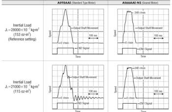
Even under the operating conditions that are optimized to reduce damping with a given inertial load, the damping characteristics of the standard type motor will deteriorate with fluctuations in inertial load. For the motor it is therefore necessary to reset the operating conditions for optimal performance each time the inertial load fluctuates. On the other hand, the geared motor's damping characteristics change little with fluctuations in inertial load, thereby ensuring steady operation.
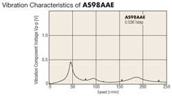
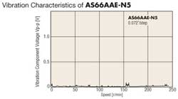
● Baixa vibração
Vibration characteristics are represented in voltage, into which the vibration width of the output shaft in rotation is converted. Vibration of the geared motor can be reduced for the following reasons:
- The motor's own vibration can be reduced in accordance with the gear ratio.
- The low speed vibration range can be avoided, since the motor rotates at higher speeds.